Description
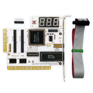
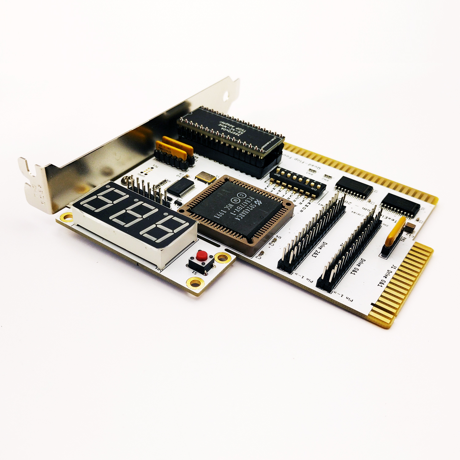
The Quad-Flop has finally arrived!
What is it?
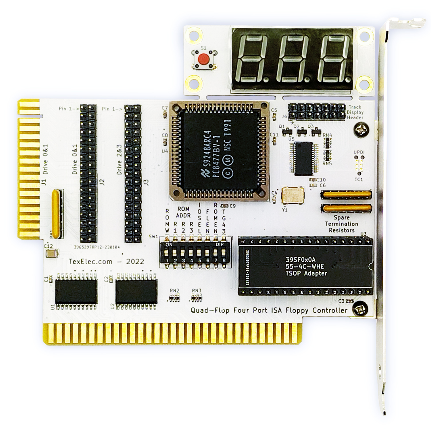
- 4-port floppy controller based on the National Semiconductor PC8477B “Advanced Floppy Disk Controller” IC.
- Atmel ATMEGA4808 microcontroller to monitor & display track position, enable TG43 and control write protection.
- Removable 3-digit display shows drive activity, current track and allows write protection with a single push.
- Track greater than 43 (TG43) for 8” drives can be enabled and used by an optional adapter.
- Removeable ‘termination’ resistor for tricky drive configuration. Includes 150, 1K & 10K ohm resistor packs.
- Supports 160K single-sided drives all the way up to 2.88MB ED disks.
- Two physical ports for drive 0 & 1, a standard 34-pin header connector, or an edge connector for use in older systems like the IBM 5150.
- Drive 2 & 3 have only a 34-pin header for connection.
- On-board ROM with Sergey Kiselev’s excellent Multi-Floppy BIOS. Allows older systems to support modern drives, among other features.
Who is it for?
- Works in any ISA based computer, if there is not an on-board controller which cannot be disabled.
- It works the same way a normal controller does, so it can be used as a drop-in replacement.
- ROM add-on allows many advanced features and BIOS configuration for floppy drives.
- Easily add 4 floppy drives to one system. Great for a universal 360K, 1.2MB and 1.44MB drive system.
- Easy cabling options for older systems.
- Enables TG43 for use with 8” floppy drives which required it. Users of 8” floppy drives will find this card easy to use.
- Add an HXC-style display to your floppy drive!
Usage:
The on-board ROM is preinstalled with Sergey Kiselev’s Multi-Floppy BIOS extension. This extension adds some great features, which include allowing the use of high density / high data-rate floppy drives on older systems which do not have support for them in BIOS. You set the drives you have, and save them to the on-board ROM. This allows booting with no driver, and no need to reset the configuration on each boot.
There are a total of 5 dip switches related to ROM functionality.
DIP Position 7 – *Enable / Disable ROM IC – *default: Enabled, disable if not needed.
DIP Position 1 – *Enable / Disable ROM write control – *default: This needs to be enabled to update the configuration.
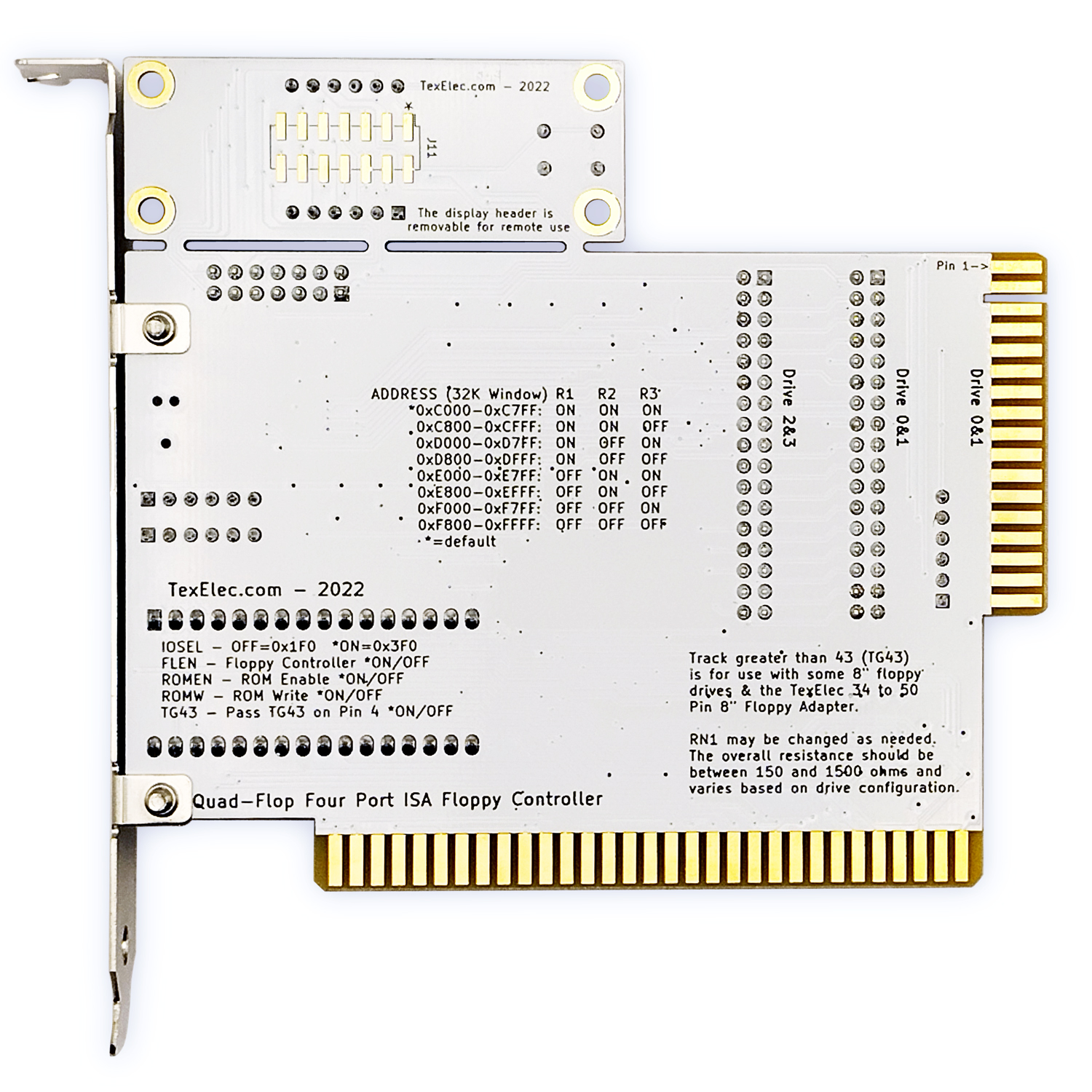
DIP Position 2-4 – ROM Address Selection
DIP Position – 2 3 4
0xC000-0xC7FF – ON ON ON
0xC800-0xCFFF – ON ON OFF
0xD000-0xD7FF – ON OFF ON
0xD800-0xDFFF – ON OFF OFF
0xE000-0xE7FF – OFF ON ON
0xE800-0xEFFF – OFF ON OFF
0xF000-0xF7FF – OFF OFF ON
0xF800-0xFFFF – OFF OFF OFF
Please check your system configuration to ensure there is no conflict with exisiting ROM in your system. I recommend using CheckIt, or some other DOS utility to analyze the ROM space to find a free location. It is also important that your system support option ROMs for the BIOS to load during POST. Many older systems, such as the IBM 5150, require a later BIOS revision for this support.
DIP Position 5 – *0x3F0(on) / 0x1F0(off) – IO Select sets the IO address for the floppy controller.
In general, there is little to no support for multiple floppy controllers in the same system. There is a documented IO port for a secondary controller, but the DMA and IRQ addresses really do not have a defined secondary location and are usually unimplemented by most computer manufacturers. However, another feature of the Multi-Floppy BIOS is to allow for two controllers in the same system for a total of 8 floppy drives. The BIOS allows sharing of the IRQ and DMA channels, only the secondary IO address will need to be changed in a two-card setup. We have not tested this ability but have included the ability to change to the secondary IO address if desired. We plan to test this soon, for now, we don’t know how reliable this mode is.
DIP Position 6 – Floppy *Enable / Disable – Enabled by default.
You may want to disable this if you have a system with an on-motherboard floppy controller, and you want BIOS support. However, it would be better to get an ISA ROM controller board as no other features of the card will function.
DIP Position 8 – TG43 *Enable / Disable – Enabled by default.
In general, it should be safe to leave this on, and can be disabled as a troubleshooting step. The signal is passed on pin 4 of the floppy cable, which is unused in most implementations. Our 8” Floppy adapter will use this signal to control TG43 on the proper pin of the 50 pin 8” floppy connector. Normally, 34-pin drives do not use this pin.
Display:
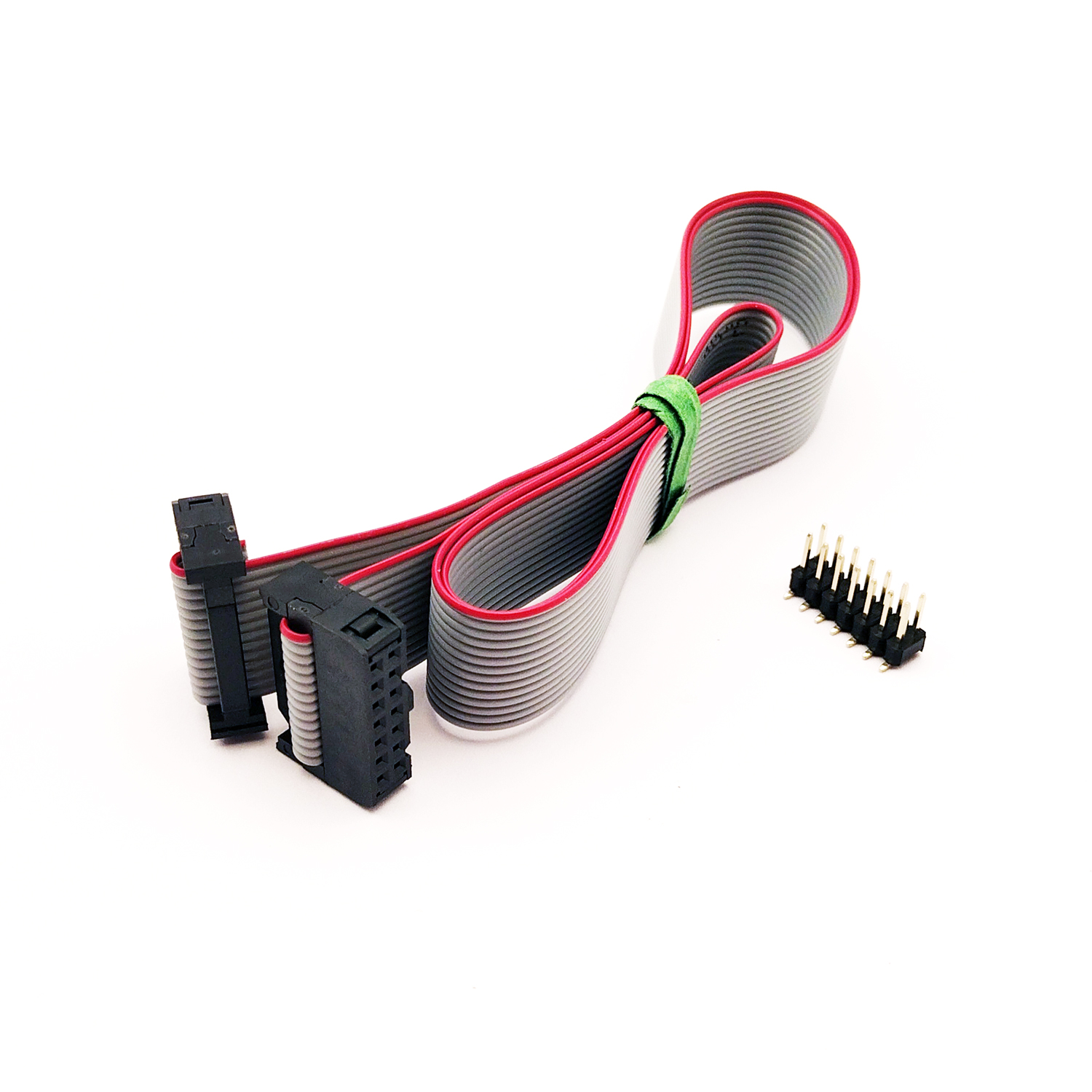
The display is preinstalled on the floppy controller, and may be used as-is with no modification. This is ideal for a bench setup, or a test machine which is open most of the time. Alternately, the display may be removed by breaking it from the floppy controller. If you prefer to use the display remotely, we include a surface mount pin-header and a small ribbon cable to mount it where you prefer. The idea was to either allow it to set on your desk, or on the top of the computer. Alternately, you could cut a hole in a blank drive bay, or wherever you like and mount the PCB on the outside of the case. You will need to solder the pins to the rear of the display to use it remotely. We decided not to install them because they may short against another card in the machine. If you plan to use the header remotely, just let us know in the notes field on the checkout screen when you order, and we’ll be happy to pre-solder it before shipping.
Notes:
The display shows the first two drives as A & B, and the third and fourth drives as E & F. This is done because drive C & D are often hard drives.
The display button will allow you to toggle the display to show drives detected by the controller. If a drive becomes active, it will take over the display immediately. You can toggle between drives only while there is no drive activity.
If you chose not to use the BIOS extension, you can also use an older driver from SUNIX call sdrive.sys. The driver is bundled in a single zip file online, the driver needed is in the \ex-3110\SDRIVE directory. We tested this before using the BIOS extension, and it works well and is easy to configure. It is nearly lost to time, but here is a link to it on Archive.org: http://www.pop-brb.de/download/treiber/exsys/ide.zip
Here is the link to Sergey Kiselev’s BIOS we use on this card: Multi-Floppy BIOS Extension (github.com)
Many thanks to Shelby from Tech Tangents on YouTube for helping us test the card during development. He released a video of the card in use here: New 4 Drive Floppy Controller – TexElec Quad-Flop
We plan to make a video on YouTube very soon showing the cards capabilities in better detail and performing more testing on multi-card configurations. Keep an eye on our channel here: TexElec
Last but not least, we highly recommend watching Curious Marc’s very comprehensive video on 8″ floppy drives. It is a great source for helping get past the infamously tricky setup of one of these drives: All you never wanted to know about 8 inch floppy drives