Description
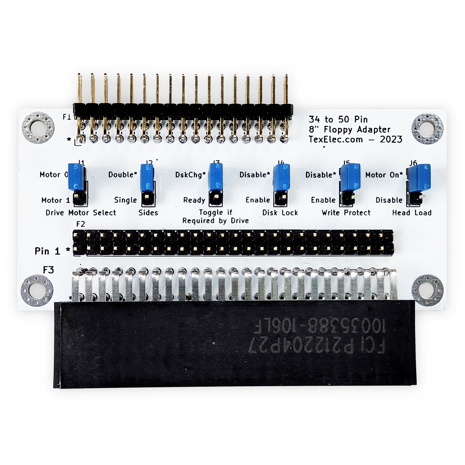
This adapter allows the use of most 50-pin Shugart interface 8-inch floppy drives on a standard 34-pin floppy controller. You can either plug the board directly into the back of an 8-inch floppy drive or use a standard 50-pin ribbon cable. This adapter will work with any standard floppy controller, however the QuadFlop controller we offer will pass the TG43 signal to 8 inch floppy drives. Some 8-inch floppy drives require TG43 or track greater than 43 to reduce the write current to the inner tracks of the disk. Drives which don’t need this signal will ignore it.
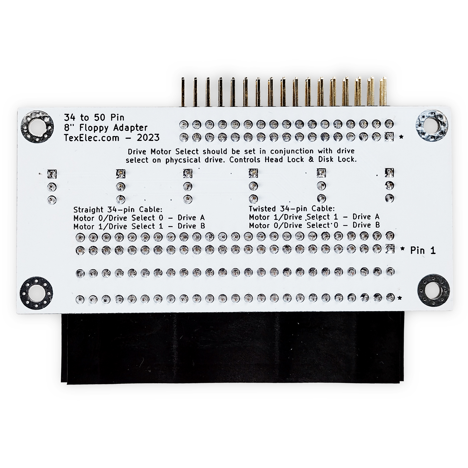
The 50-pin 8-inch floppy interface supports four floppy drives on one cable, however 34-pin interfaces only support two. In addition, the 34-pin floppy cable used by PCs has a twist in the cable to determine which drive is A and which is drive B. This makes drive installation simpler and results in 5.25-inch and 3.5-inch drives being set to device 1 or drive B by default. The twist in the cable will swap the pins around to make a drive set to B respond to signals sent to drive A. The floppy adapter passes the 34-pin signals from drive A and B along to the 50-pin 8-inch interface directly. The third and fourth drives are not accessible via this interface, you will need to set your 8″ drive to either 0 or 1. Whether or not this results in drive A or B to the system will depend on whether there is a twist in your floppy cable or not.
The adapter has several jumpers which allow configuration of common settings needed for 8-inch floppy drives. The default settings will work with most drives, but there may be situations where you may need to make changes. It is important that you consult the manual or datasheet for your device to understand the requirements. 8-inch floppy drives generally have more flexibility than newer drives, but this means they may be a little more difficult to configure for use with a standard PC interface.
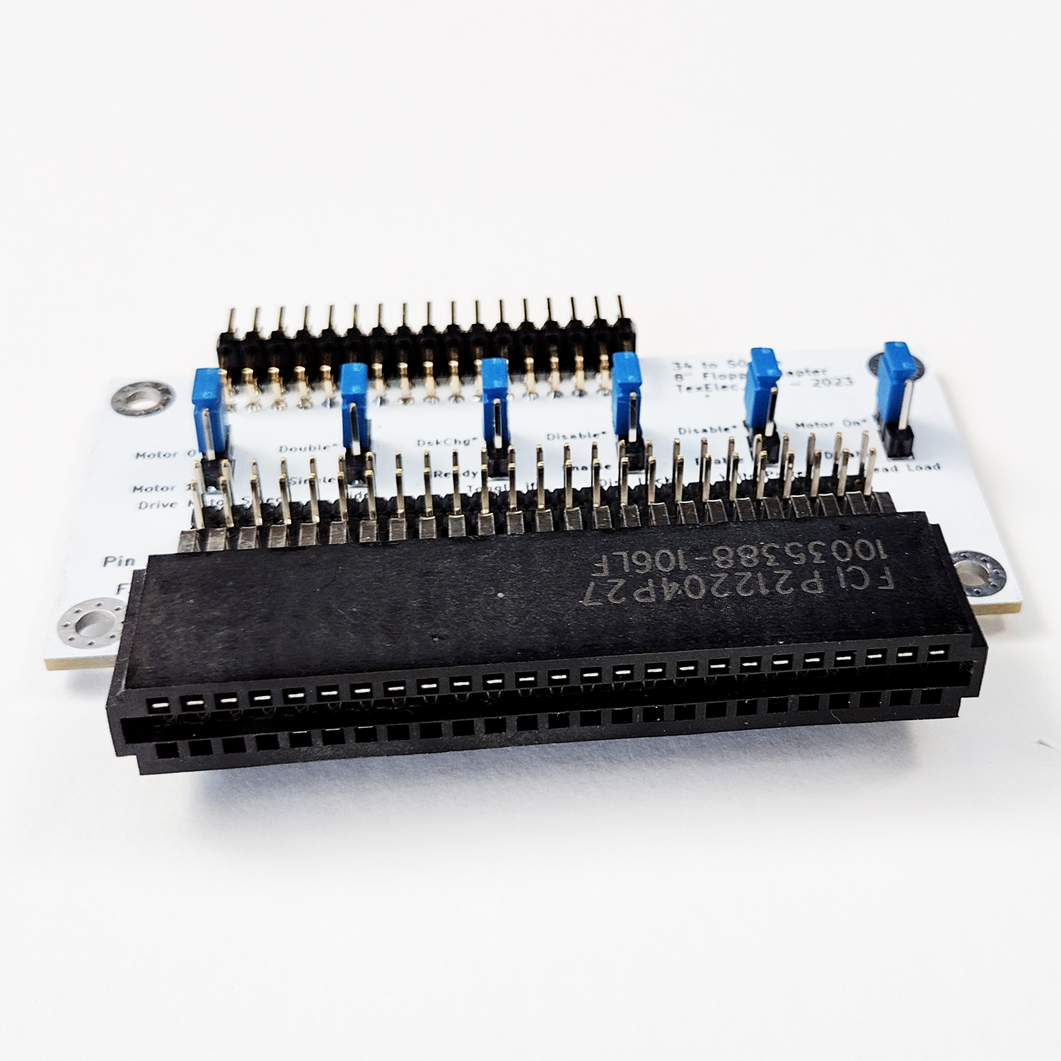
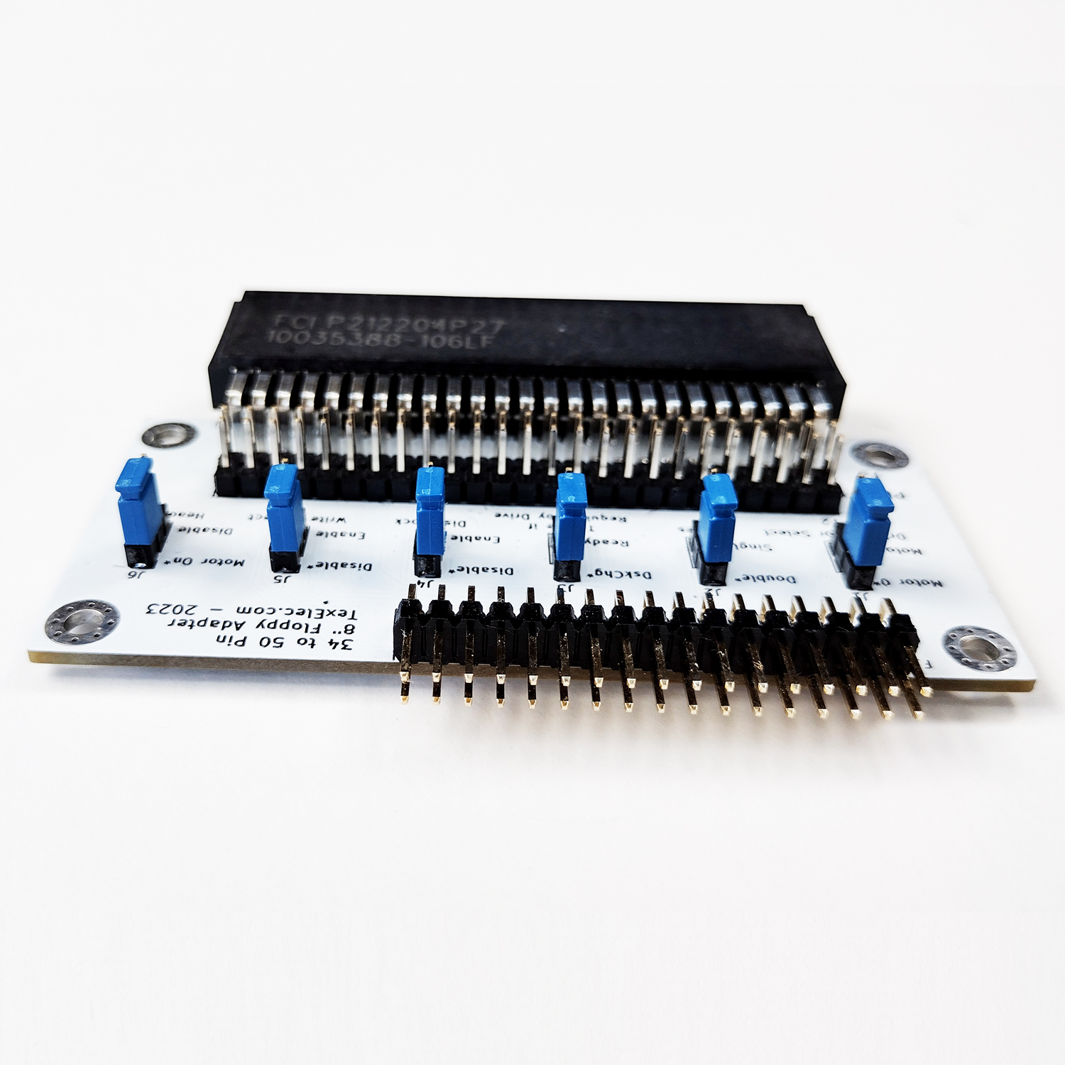
Jumper Settings:
J1 – Drive Motor Select – *Motor 0 / Motor 1 – This setting will change the Motor Select line used for Head Loading and for Disk Locking. This signal will follow the twist of the cable and should not need to be changed.
J2 – Sides –*Double / Single – Tells the drive if the interface supports one or two sides. The default is double-sided, but it can be changed if desired.
J3 –Disk Change – *Disk Change / Ready – Most drives use a standard pin for notifying of a disk change, but other drives use the ready line to indicate a change. Only change if needed by your device.
J4 – Disk Lock – *Disable / Enable – This setting will enable disk door locking when the motor for the drive is selected, if configured and supported by your device.
J5 – Write Protect – *Disable / Enable – Handy for preventing accidental erasure during disk archiving.
J6 – Head Load – *Motor On / Disable – Some drives raise and lower the disk heads depending on access. This setting uses the Drive Motor Select line to enable this signal. The disable setting means no signal is sent to the device. Many drives will automatically enable the heads when accessed. This setting may need to be changed based on your device configuration.
(*default setting)