
Description
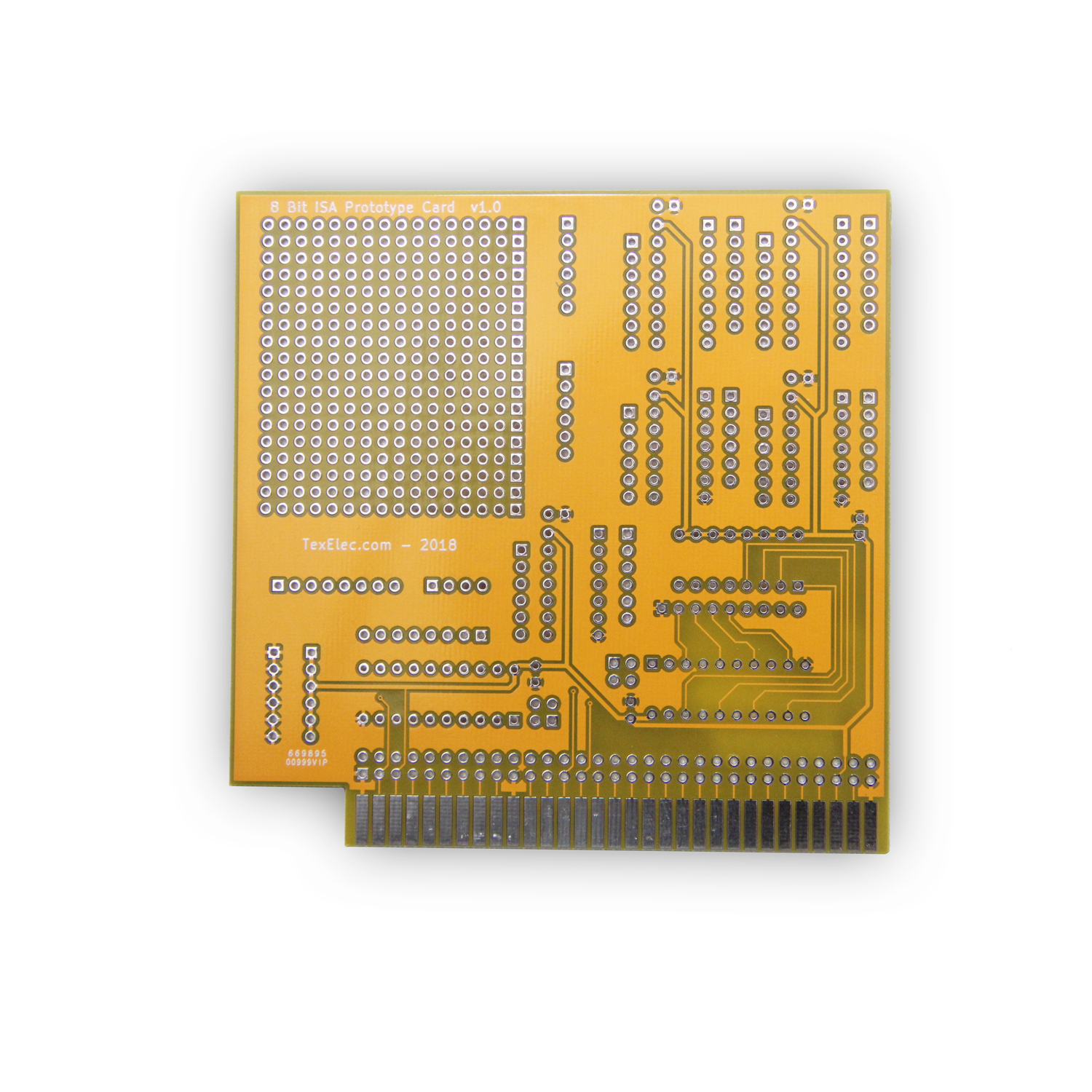
8 bit ISA Prototype Card v1.0 – For Vintage PCs
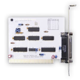
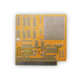
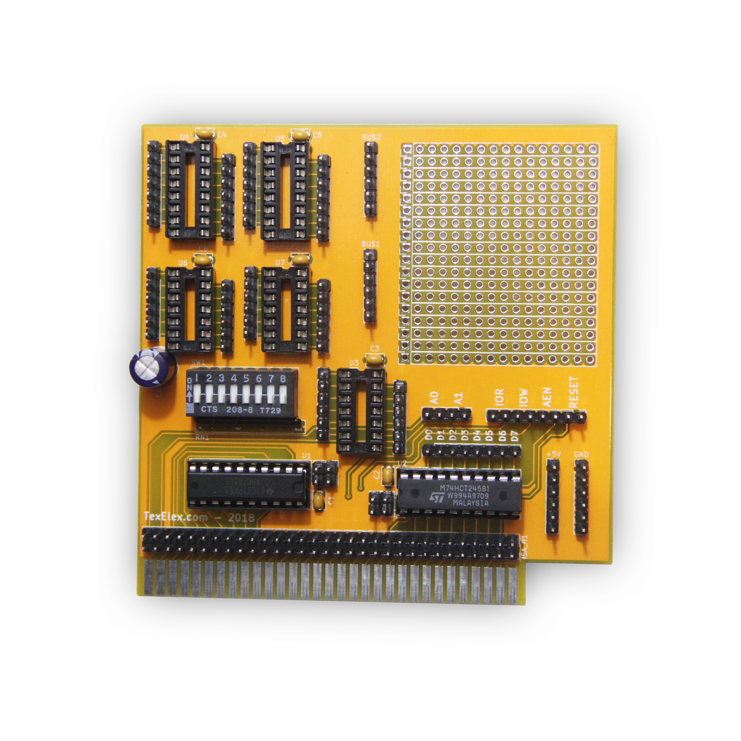
The assembled card in the photos is for reference only, when you order the card you will receive the bare PCB.
We built this card to help with development of a few products we are working on. It turned out so well, we thought we would make it available for the DIY community. The board is really meant to help you easily design a device which uses an I/O port and talks to the data bus bidirectionally. Things like parallel ports, serial ports, sound cards, etc. It is not really meant for decoding memory addresses, although you can theoretically connect to any pin you wish on the bus, so the sky’s the limit. The boards are being sold as bare PCBs as not everyone will need every single pin. You can just install what you need, and add things as go if more is needed.
The card has two rows of pins on the bottom of the card you can add to allow access to any pin on the ISA slot. You can connect to the IRQ lines here if needed. There are only two required ICs, one 74HCT688 used for port address decoding and one 74HCT245 bus transceiver IC. The 74HCT688 has a bank of 8 dip switches and a 9-pin common-bus 10k resistor pack, which allows you to select any I/O port from 0x000 – 0x3FC!** Pin 1 & pin 19 on the 74HCT688 & 74HCT245 have two pins exposed each on the board. Pin 1 on the 74HCT688 is enable & 19 is used when the port matches the dip settings. Pin 1 on the 74HCT245 sets the bus direction & 19 is used to enable/disable the IC. Address Pins A0 & A1, IOR, IOW, AEN & RESET all have two pins each exposed which allow you to easily wire up the lines needed for your prototype device. Pins D0-D7 are also exposed. There are five IC sockets, two 16-pin & three 14-pin with header pins for whatever ICs you would like to add. They are connected on pin 8 to GND & pin 16 to +5v, so if your IC is wired differently than this, be aware. There are two 6 pin ‘bus’ connections to the right of the IC sockets, which are just connected together on the board. This is a way to allow you to connect a few wires together easily if you need. There are six +5v and six ground pins on the lower right-hand of the board for grounds and power connections if needed. Lastly, there is a 16 x 18 pin prototype area on the board. That’s 288 pins for anything you want to add!
All ICs also have space for a 0.1uf decoupling capacitor, and there is room for an electrolytic capacitor on the board to make sure there is enough reserve current. I put a 100uf 50v on my board, which is overkill, I just have them on hand. You can safely use a 16v capacitor and the value is up to your needs. 47uf will likely be more than enough for most.
** (Some addresses are invalid of course, but this gives you complete flexibility. It allows you to select the state of A2-A10 I/O lines. For Example, port 0x378 is 11 0111 1000 in binary. For this port you would set the dip switches to 1101 1110. The last two bits are used to address your device on ports 0x378 – 0x37B.)
This card is for hobbyists and prototypers. On it’s own, it doesn’t do much, but it will allow you to quickly select an address and talk to the bus for anything you would like to design. Please let us know if there is any interest in a 16-bit version, or any suggestions for a better prototype card!
We buy most of our parts from Mouser.com. For quick reference, here is a list of needed parts:
1 – 8 Pin Dip Switch – Mouser Part # 774-2088
1 – 10k 9 Pin Resistor Pack – Mouser Part # 858-L091S103LF
1 – 74HCT688 IC – Mouser Part # 595-CD74HCT688E
1 – 74HCT245 IC – Mouser Part # 595-SN74HCT245N
1 – 47uf 16v Electrolytic – Mouser Part # 647-UVR1C470MDD1TD
2 – 0.1uf MLCC Caps – Mouser Part # 594-K104K15X7RF53L2 (You may want more for optional ICs)
In addition, you may want to buy 14 & 16 pin IC sockets. You will also need 2.54mm or 0.1″ spaced header pins for any pins you want to add.
I recommend getting these from eBay as you can buy several hundred pins for only a few dollars. You can use male or female pins, just be sure you also get some jumper wires which correspond to your pin choice. If I added correctly, it takes a total of 178 header pins if you wish to populate everything on the board.
We are making the schematic available. You may download the PDF here: https://texelec.com/wp-content/uploads/2018/04/ISA-Device-Board.pdf